If you happen to own a golf cart with a hall effect sensor, such as found in the RXV's, TXT's, and many others, and you also happen to know how to use an Arduino...
You might be interested to know that you can actually test a throttle position sensor using the Arduino and just three wires.
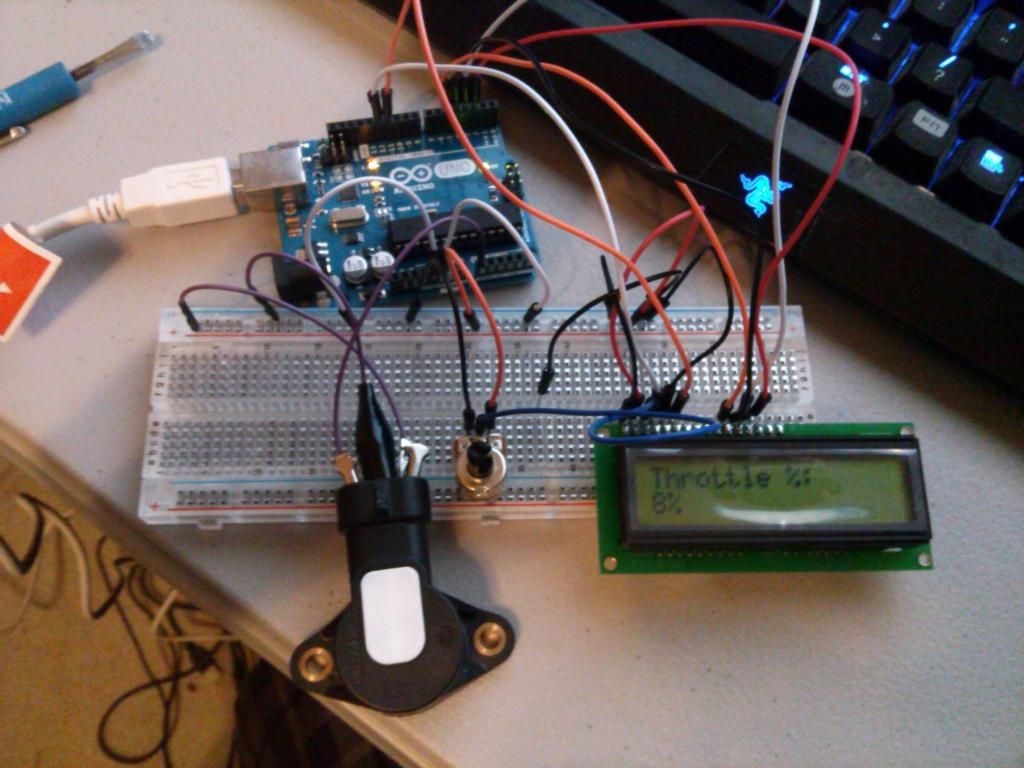
The hall effect sensor I tested was a throttle position sensor from an early EZGO RXV. This sensor uses a 5V supply from the controller, then returns the modified signal to the ECU, and uses a ground from the controller.
By connecting the Arduino's 5V supply and ground to two of the pins, you can then connect the signal pin to an analog pin on the Arduino and map the voltage to a known value between 0 and 1023. A little simple math and you have a throttle percentage.
Considering how expensive the sensors can be, and the fact that the RXV for example has no less than three of these sensors, it can be a pretty valuable little tool. You could also use the Arduino to replace the brake and throttle sensors and convert the cart from the stock pedal controls to any control interface you wanted.
Why would you want to do that? Perhaps you have a handicapped individual who cannot use their feet. Remapping the controls to levers on the steering wheel would allow them to drive the car and retain all of the original features without adding complicated levers or mechanical systems to push the pedals. You could actually remove the pedals entirely.
I can post more details if anyone is interested, otherwise just thought I would share a little experimentation. I did it since we don't have an oscilliscope at our dealership, and was looking for an easy way to test hall effect sensors off the cart.