
|
|
|||||||
| Electric Club Car Electric DS, and Precedent golf cars |
  |
|
|
Thread Tools | Display Modes |
 07-16-2013, 09:12 PM
|
#1 |
|
Not Yet Wild
Join Date: Jun 2013
Posts: 11
|
Greetings,
Posted this question in another :) forum, but so far, absolutely no replies. so... can anyone please offer some thoughts? Thanks so much! ....................... For the life of me, I cannot figure out the wiring on a 1990 resistor (no solenoids) cart. The motor has to turn backwards, like all other carts. What makes this one difficult, is the wiring diagram does not electrically show what the F/R switch is doing inside. Most others, like the newer controller carts, the F/R switch switches the direction of the current across the armature -one way across A1 to A2 for forward, the other way across the armature for reversing the motor. So it MUST change the direction of the current across the armature, but I cannot find a wiring diagram that illustrates how the F/R switch does that. Unlike the additional spread sheet type of boxes shown on newer wiring diagrams. Years ago, still listed in the "resources" section, was an excellent post from "doc" illustrating current flow (copied below). But for reverse, unless my eyes are going crazy, other than the different (lower) voltage tap for reverse, the author traces the same - direction - path. Anyone already figure this out????? Naturally, if the current flow in reverse, through the coils and solenoid, what to expect troubleshooting with a volt meter will be completely different. Thanks so much. Bill >>>>For the purpose of this sequence we will use flow from battery positive to battery negative. Starting from battery number one positive post current will flow from the red cable to the forward lug on the F/R (forward/reverse) switch assembly. Current will then flow to the R3 resister (white cable). When the Master Solenoid is energized (activated) along with 1st speed solenoid current will flow though the resisters (R3, R2 and R1) to A2 at the motor (white cable). Current will then flow through the armature to A1 then to the Moving Contact on the F/R switch assembly. From the Common Lug current will flow (red cable) to S1 on the Drive Motor, though the fields and out to S2. From S2 (black cable) current will flow to battery negative at battery number six post. This completes the power flow for the forward mode at low speeds. As each Solenoid is activated (energized) speeds will increase to peak potential. When the shifter is moved into the reverse position the flow is from battery number four (red cable) positive post to the reverse lug on the F/R shifter. Current then flows (white cable) to R3, R1 and R1 resister and as the Master Solenoid and 1st speed solenoid is activated (energized) current will flow (white cable) to A2 at the Drive Motor. Current will then flow through the armature to A1 at the motor. From A1 current will flow (black cable) to Moving Contact on the F/R assembly. Current will then flow (red cable) to S1 at the drive motor and through the fields to S2. From S2 current will flow (black cable) to battery negative at Battery number six negative post. This completes ? speed reverse. For the activation circuit current will flow from the F/R forward lug to the speed switch (yellow wire). Notice this positive potential is fed to all five micro switches (common terminal). As each switch is activated this positive potential is applied to each solenoid in sequence (master, 1, 2, 3 and 4). The negative to the solenoids will be applied from the negative at the charging receptacle red wire to the key switch. From the key switch negative will be applied to the Anti-Arcing micro switch located on the F/R assembly (common terminal). From the normally open terminal negative will be applied to the solenoids (yellow wire). Again, notice that this negative potential is supplied to all five terminals on the solenoids. This completes the sequence for activation. For trouble shooting this system a volt/ohm meter is all you will need. By understanding the flow (sequence) you can at this point find the missing potential though the circuit. |

|

|
 Today Today
|
|
|
__________________
This advertising will not be shown in this way to registered members. Register your free account today and become a member on Buggies Gone Wild Golf Cart Forum |
|
|
07-19-2013, 11:28 AM
|
#2 |
|
Not Yet Wild
Join Date: Jun 2013
Posts: 11
|
Any ideas, please??????
|
|
|
|
|
07-19-2013, 11:38 AM
|
#3 |
|
Rode hard, put up wet!

 Join Date: May 2013
Location: Southeast Missouri
Posts: 458
|
Bill...I just used Bing search engine and found tons of wiring diagrams for Club Car...I searched 1990 Club Car wiring diagram....check it out and maybe you can find the exact one you need.
|
|
|
|
|
07-19-2013, 11:59 AM
|
#4 |
|
Not Yet Wild
Join Date: Jun 2013
Posts: 11
|
Hi Lance,
Thanks very much for posting, seems no one has an idea. I do have 1 or 2 good diagrams; however, they exclude the internal wiring for the F/R switch. So.... I can't understand the path of the current when in reverse. I have found "external": wiring - which wire to put on which post, for example. Hopefully, someone has already been through this and can help. thanks again, Bill |
|
|
|
|
07-19-2013, 12:35 PM
|
#5 |
|
Guest
Posts: n/a
|
bill
the yearly 1990's resistor (no solenoids) carts runs the motor backwards buy taking power from the # 3 battery positive @ 18v (green wire) through the f/r switch to the motor .. the v glide still controls the amount of power supplied to the motor through the resistor 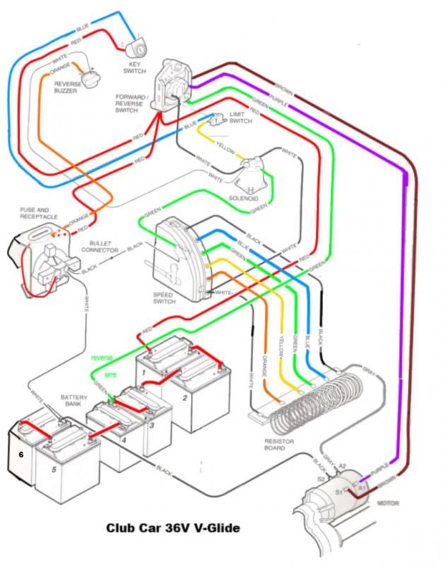 |
|
|
|
07-19-2013, 01:56 PM
|
#6 | |
|
Rode hard, put up wet!
Join Date: May 2013
Location: Southeast Missouri
Posts: 458
|
Quote:
|
|
|
|
|
|
07-19-2013, 04:52 PM
|
#7 |
|
Not Yet Wild
Join Date: Jun 2013
Posts: 11
|
Crash Test....
THANKS so much for responding! I've reads the boards, and have learned so much thu the years. I've also noted you've helped so many people. The diag with colors is awesome! CTD, Lance............. same repeated story here, helping neighbor, good guy. Naturally, I have to understand, or I won't be able to use the diagram for troubleshooting. I know the extra tap, 18V (green wire) U pointed out, also keeps the reverse speed down. You mention that the positive 18V goes thu the f/r switch, to the motor. But......... HERE's my sticking point........... the 36 (full voltage) has to go in one direction thu the motor for reverse, and the 18v has to go the opposite direction thu the motor. And, as there's no internal diag for the f/r switch, I cant see how the change of direction for the flow is made. sorry, guys, on repeating myself. :) And I really, really appreciate the help. Bill |
|
|
|
|
07-19-2013, 05:35 PM
|
#8 |
|
Guest
Posts: n/a
|
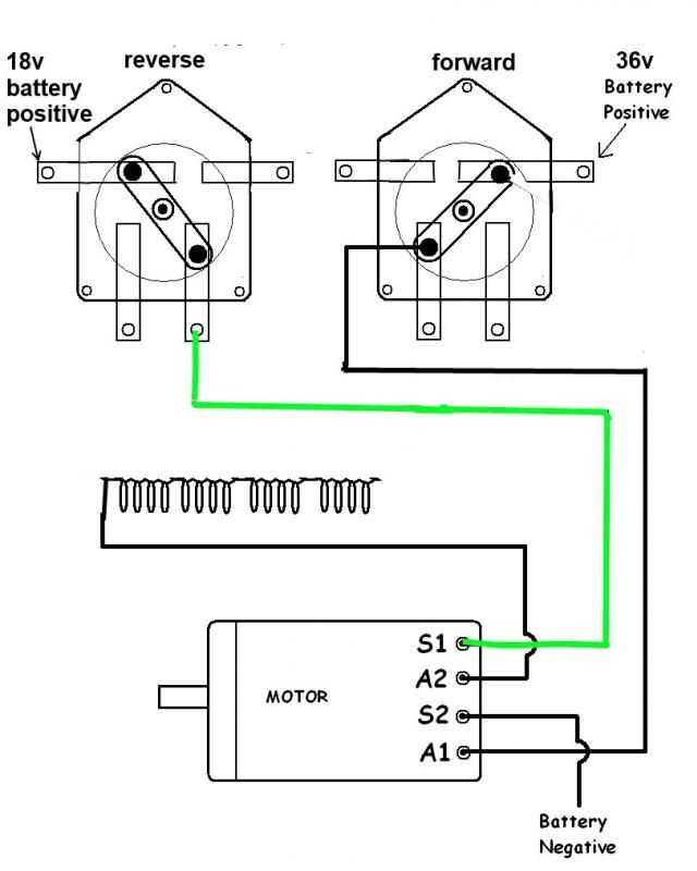
OK .. the power flows the same forward or reverse , the deference is that the f/r switch routes it to a different lug on the motor (1 forward & 1 reverse)
energizing motor with reverse polarity causes motor to run backward note the brown and purple wires so 1 makes it go forward the other goes backwards Last edited by crash test dummy; 07-19-2013 at 05:55 PM.. Reason: opps |
|
|
|
07-19-2013, 06:03 PM
|
#9 |
|
Guest
Posts: n/a
|
best i can do
 |
|
|
|
07-19-2013, 11:51 PM
|
#10 |
|
Gone Wild
Join Date: Sep 2012
Location: Charlotte, NC
Posts: 9,329
|
I added some color to ctd pictures to show the current flow under both positions, does this help?
|
|
|
|
|
|
||||||
| Thread Tools | |
| Display Modes | |
|
|
 Similar Threads
|
||||
| Thread | Forum | |||
| Motor want run in reverse | Electric EZGO | |||
| motor runs only in reverse | Electric EZGO | |||
| Reverse alarm stuck - motor won't run forward or reverse | Electric EZGO | |||
| motor runs in reverse | Electric Yamaha | |||
| Motor will not go in reverse | Electric EZGO | |||


 Linear Mode
