lifted club cars - lifted ezgo
Home FAQDonate Who's Online
Go Back   Buggies Gone Wild Golf Cart Forum > Golf Cart Repair and Troubleshooting > Electric EZGO
Electric EZGO Electric EZ GO Marathon, Medalist, TXT and RXV.


Post New Thread  Reply
 
Thread Tools Display Modes
Old 09-18-2017, 07:06 PM   #11
scottyb
Happy Carting
 
scottyb's Avatar
E-Z-GO
 
Join Date: Dec 2007
Location: Southern California
Posts: 73,419
Default Re: EZGO DCS problems

Quote:
Originally Posted by atr42flyer View Post
Scotty,
I was hoping you would respond. When you got JB - you don't need me

It is a 1996 Ezgo TXT DCS, It didn't have a diode between the two small terminals on the old solenoid.

But I did buy a brand new recharge resistor https://diygolfcart.com/solenoid-res...CABEgJRrfD_BwE

The controller popped last night. So I need to send it back for repair. (again)

on a DCS cart is the smaller diode required? I did not see one on the wiring diagram. The Curtis control requires the 250Ω precharge resiostor and the 1 -3 amp arresting diode

I will try and upload a pic of the solenoid later
Quote:
Originally Posted by mutant View Post
put an alltrax in it...

Repaired controllers is the epitome of good money after bad
scottyb is offline   Reply With Quote
Alt Today
BGW

Golf car forum Sponsored Links

__________________
This advertising will not be shown in this way to registered members.
Register your free account today and become a member on Buggies Gone Wild Golf Cart Forum
   
Old 09-19-2017, 07:12 AM   #12
mutant
Gone Wild
E-Z-GO
 
Join Date: Aug 2014
Location: fletcher,nc
Posts: 601
Default Re: EZGO DCS problems

DCS controllers have a fatal flaw and to rebuild is kinda like...... well,you see-i had this dog and he would not come when i called him-so i went over and started beating him-but he was dead..........................................
mutant is offline   Reply With Quote
Old 09-19-2017, 10:40 AM   #13
atr42flyer
Not Yet Wild
 
atr42flyer's Avatar
E-Z-GO
 
Join Date: Jul 2015
Location: Lakeland, TN
Posts: 67
Default Re: EZGO DCS problems

Quote:
Originally Posted by mutant View Post
DCS controllers have a fatal flaw and to rebuild is kinda like...... well,you see-i had this dog and he would not come when i called him-so i went over and started beating him-but he was dead..........................................
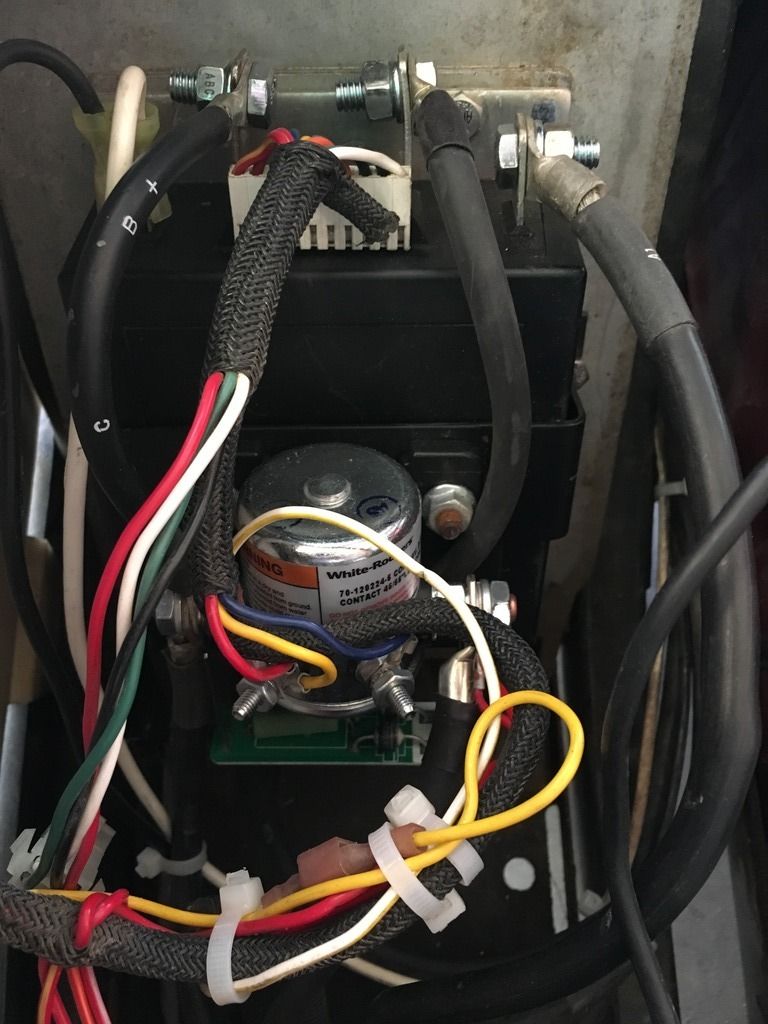
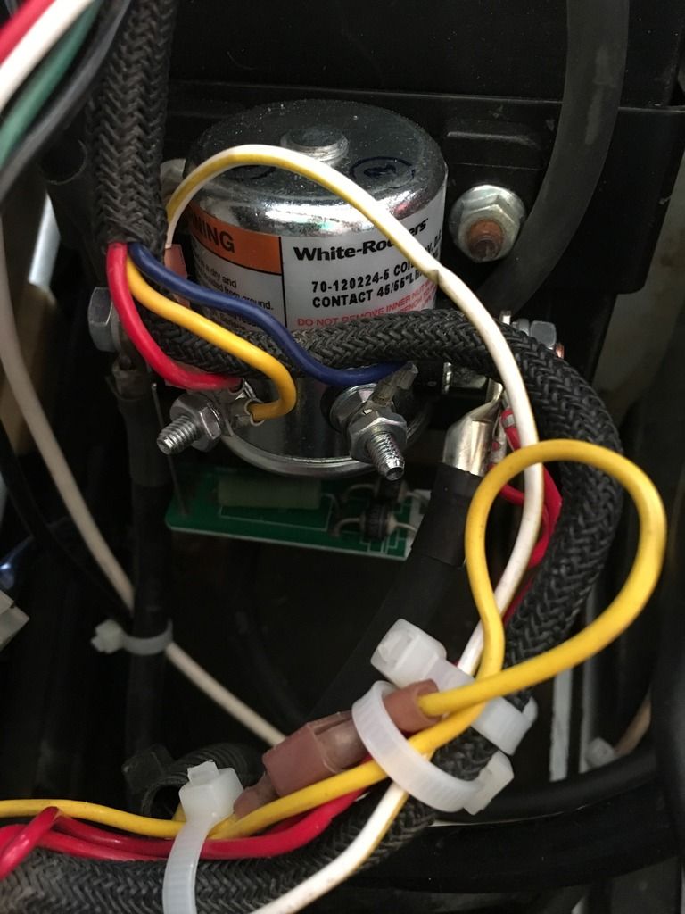
lol ok ok ok I get it, but still I want to know what the heck went wrong. Here are some pics of the solenoid. where did I goof up?


Last edited by atr42flyer; 09-19-2017 at 10:44 AM.. Reason: pics
atr42flyer is offline   Reply With Quote
Old 09-19-2017, 11:27 AM   #14
atr42flyer
Not Yet Wild
 
atr42flyer's Avatar
E-Z-GO
 
Join Date: Jul 2015
Location: Lakeland, TN
Posts: 67
Default Re: EZGO DCS problems

So I think I may have figured out where I went wrong. I have the A2 wire from the motor going to the solenoid. I have looked at other pictures and it appears to go to the B+ terminal on the controller?
On the wire diagram I was using from this site shows it going to the solenoid, so thats my excuse for wiring that way but it kinda makes sense, that is the reason for the B+ wire from the controller to the solenoid got so hot and running at half speed.

Opinons?
atr42flyer is offline   Reply With Quote
Old 09-19-2017, 11:53 AM   #15
JohnnieB
Techno-Nerd
 
JohnnieB's Avatar
E-Z-GO
 
Join Date: Jun 2011
Location: West Virginia
Posts: 19,654
Default Re: EZGO DCS problems

If the cable on the large solenoid terminal on the right side of the pictures is from the B+ terminal on the battery pack, the Diode/Resistor PCB assembly is installed correctly.

I cannot tell from the pictures, but if the small white wire with yellow stripe is connected the the left side small terminal that also has a red and a yellow wire on it, the control wiring is correct also.

Neither the DCS nor the PDS had a discreet diode between the small solenoid terminals as it came from the factory, but adding one is probable a good idea. I suspect a spike suppression diode was incorporated within the controller.

The Diode/Resistor PCB was unique to the DCS. The PDS only had a pre-charge resistor between the large terminals.

This is speculation, but I suspect the diodes on the DCS PCB were there to prevent the controller from being over-volted if the solenoid de-energized while regen braking was occurring. I'm not sure why regen diodes weren't used for PDS drives, perhaps they were incorporated inside the controller.
FWIW: Alltarax XCT controllers for DCS, PDS and TXT-48 all have regen diodes and spike suppression diodes, but no pre-charge resistors.

----------
I noticed the A2 cable is original and the cable lug doesn't look very good. That may be the heat source.
JohnnieB is offline   Reply With Quote
Old 09-19-2017, 12:05 PM   #16
atr42flyer
Not Yet Wild
 
atr42flyer's Avatar
E-Z-GO
 
Join Date: Jul 2015
Location: Lakeland, TN
Posts: 67
Default Re: EZGO DCS problems

Quote:
Originally Posted by JohnnieB View Post
If the cable on the large solenoid terminal on the right side of the pictures is from the B+ terminal on the battery pack, the Diode/Resistor PCB assembly is installed correctly.

I cannot tell from the pictures, but if the small white wire with yellow stripe is connected the the left side small terminal that also has a red and a yellow wire on it, the control wiring is correct also.

Neither the DCS nor the PDS had a discreet diode between the small solenoid terminals as it came from the factory, but adding one is probable a good idea. I suspect a spike suppression diode was incorporated within the controller.

The Diode/Resistor PCB was unique to the DCS. The PDS only had a pre-charge resistor between the large terminals.

This is speculation, but I suspect the diodes on the DCS PCB were there to prevent the controller from being over-volted if the solenoid de-energized while regen braking was occurring. I'm not sure why regen diodes weren't used for PDS drives, perhaps they were incorporated inside the controller.
FWIW: Alltarax XCT controllers for DCS, PDS and TXT-48 all have regen diodes and spike suppression diodes, but no pre-charge resistors.

----------
I noticed the A2 cable is original and the cable lug doesn't look very good. That may be the heat source.
in the Top pic, the cable labeled B+ got super hot, goes to left side (looking at pic) of the solenoid, also then connects left side of solenoid to the A2 wire on the motor.

Last edited by atr42flyer; 09-19-2017 at 12:06 PM.. Reason: carity
atr42flyer is offline   Reply With Quote
Old 09-19-2017, 12:09 PM   #17
atr42flyer
Not Yet Wild
 
atr42flyer's Avatar
E-Z-GO
 
Join Date: Jul 2015
Location: Lakeland, TN
Posts: 67
Default Re: EZGO DCS problems

Quote:
Originally Posted by JohnnieB View Post

----------
I noticed the A2 cable is original and the cable lug doesn't look very good. That may be the heat source.
Ok I will get a new cable for that for sure.
atr42flyer is offline   Reply With Quote
Old 09-19-2017, 12:13 PM   #18
JohnnieB
Techno-Nerd
 
JohnnieB's Avatar
E-Z-GO
 
Join Date: Jun 2011
Location: West Virginia
Posts: 19,654
Default Re: EZGO DCS problems

Quote:
Originally Posted by atr42flyer View Post
So I think I may have figured out where I went wrong. I have the A2 wire from the motor going to the solenoid. I have looked at other pictures and it appears to go to the B+ terminal on the controller?
On the wire diagram I was using from this site shows it going to the solenoid, so thats my excuse for wiring that way but it kinda makes sense, that is the reason for the B+ wire from the controller to the solenoid got so hot and running at half speed.

Opinons?
The short cable to B+ on the controller and the A2 cable were both on the solenoid's controller side large terminal as it came from the factory. I'm not sure why EZGO did it that way, perhaps it used less cable. Cursory inspection says the controller side large terminal and the B+ terminal on the controller are the same point electrically, but there are two circuits involved (Motor current and Battery current) and how much current flows in the short cable is different, depending on where the A2 Cables is connected.

When the duty cycle of the PWM output of the controller is anything other than 0% or 100%, the Motor current is greater than Battery current, so the most efficient way to connect those two cables is the stack them on the controller's B+ terminal. However, the way those two cable are connected is not the source of your heat problem.
JohnnieB is offline   Reply With Quote
Old 09-19-2017, 12:16 PM   #19
JohnnieB
Techno-Nerd
 
JohnnieB's Avatar
E-Z-GO
 
Join Date: Jun 2011
Location: West Virginia
Posts: 19,654
Default Re: EZGO DCS problems

Quote:
Originally Posted by atr42flyer View Post
Ok I will get a new cable for that for sure.
There are 10 high current cables in a DCS drive and all ten ought to be replaced.

The A1 and B- cables look original also.
JohnnieB is offline   Reply With Quote
Old 09-19-2017, 01:22 PM   #20
atr42flyer
Not Yet Wild
 
atr42flyer's Avatar
E-Z-GO
 
Join Date: Jul 2015
Location: Lakeland, TN
Posts: 67
Default Re: EZGO DCS problems

Quote:
Originally Posted by JohnnieB View Post
There are 10 high current cables in a DCS drive and all ten ought to be replaced.

The A1 and B- cables look original also.
yes I replaced 7 cables already and will purchase the other 3
atr42flyer is offline   Reply With Quote
Reply
Go Back   Buggies Gone Wild Golf Cart Forum > Golf Cart Repair and Troubleshooting > Electric EZGO


Similar Threads
Thread Forum
Ezgo problems, Electric EZGO
02 ezgo problems Electric EZGO
84 EZGO Problems Gas EZGO
Problems with EZGO TXT Gas EZGO
06 EZGO PDS problems Electric EZGO


All times are GMT -5. The time now is 09:43 PM.


Club Car Electric | EZGO Electric | Lifted Golf Carts | Gas EZGO | Used Golf Carts and Parts

Powered by vBulletin® Version 3.8.9
Copyright ©2000 - 2024, vBulletin Solutions, Inc.
This Website and forum is the property of Buggiesgonewild.com. No material may be taken or duplicated in part or full without prior written consent of the owners of buggiesgonewild.com. © 2006-2017 Buggiesgonewild.com. All rights reserved.