
|
 01-06-2019, 11:35 PM
|
#1501 | |
|
......................
 Join Date: Apr 2009
Location: FT Lauderdale FL.
Posts: 16,416
|
http://www.buggiesgonewild.com/elect...le-locker.html
~~~~~~~~~~~~~~~~~~~~~~~~~~~~~~~~~~~~~~~~~~~~~~ Club car gas rear end Quote:
|
|

|

|
 Today Today
|
|
|
__________________
This advertising will not be shown in this way to registered members. Register your free account today and become a member on Buggies Gone Wild Golf Cart Forum |
|
|
01-09-2019, 10:13 PM
|
#1502 |
|
......................
Join Date: Apr 2009
Location: FT Lauderdale FL.
Posts: 16,416
|
This should help
http://www.ezgogolfcartguide.com/rep.../brake-system/ 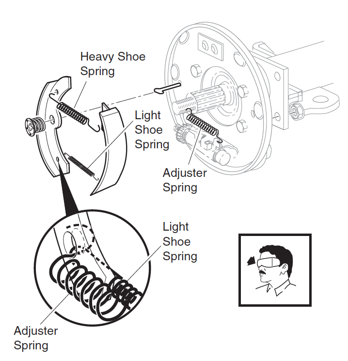 ~~~~~~~~~~~~~~~~~~~~~~~~~~~~~~~~~~~~~~~~~~~~~~~~~ Ezgo marathon electric cart  ~~~~~~~~~~~~~~~~~~~~~~~~~~~~~~~~~~~~~~~~~~~~~~~  http://www.buggiesgonewild.com/editp...&postid=644356 |
|
|
|
|
01-11-2019, 04:31 PM
|
#1503 |
|
Admin

Join Date: Dec 2006
Location: TN
Posts: 101,872
|
http://www.buggiesgonewild.com/gener...ne-wild-3.html
Here's the story behind who named this forum: I was sitting at my computer desk in the living room on the phone with Johnny (roady89). The Dungeon (beginning forum) was becoming popular and we had been trying to think of another good name for days. I actually had a spiral notebook with pages of notes and names. I had also searched the internet for ideas, etc... Anyway, I was on the phone with Roady for a while and we were discussing it and throwing all kinds of crazy names out for discussion like we'd been doing for days. My wife who was about 10 feet away from me was washing dishes and looking out the window. She overheard our conversion and said "what's going on"? I said Roady and I are trying to come up with a cool name for the forum because it is getting popular and we want to go full time with it. She never even blinked and said "why don't ya'll call it Buggies Gone Wild". I was like WOW, what the heck, we've been working on this for days, notebooks full of notes, endless columns of names, etc...  So, to give full credit where it is due, my wonderful and beautiful wife TJ, who is obviously much more creative and intelligent than me (and Roady), named this forum while washing dishes and peering out the window across our lower field. Love her!  |
|
|
|
|
|
|
|
01-11-2019, 05:24 PM
|
#1504 |
|
Gone Wild
Join Date: Sep 2018
Posts: 791
|
http://www.buggiesgonewild.com/elect...ml#post1576485
You can see how much bigger the limited slip unit is compared to the earlier ones. That's obviously why the standard plates and springs will not fit. |
|
|
|
|
01-13-2019, 12:42 PM
|
#1505 |
|
Gone Mad

Join Date: Oct 2009
Location: Buford, GA
Posts: 8,988
|
http://www.buggiesgonewild.com/elect...ml#post1577101
This is about as simple a DC circuit as you can find, once you get used to it. Print out the attached, and follow the circuit until you understand it. From Battery Pack Negative, follow the wire on the diagram to Controller B-, then to Solenoid and to Backup Beeper. From Solenoid, to Controller Pin 1 and MS3, to KS1, to MS2, to Diode, to Fuse, to Charger Positive, to Interlock (reed switch), to Battery Pack Positive. Diode and Fuse are recommended by Alltrax, and may not be installed. Neither are necessary, but if youd're spitting sparks and are having a hard time following the wiring diagrams and using a DMM, you may want to consider adding them. MS2 is only closed (on) when the Forward, Neutral, Reverse (FNR) switch is in Forward or Reverse, and is open (off) when FNR is in Neutral. MS4 is only closed when the FNR is in Reverse. When MS4 is closed, the Backup Beeper sounds, and Controller Pin4 tells the Controller to operate at half speed. From Backup Beeper, to Controller Pin 4 and MS4, to Diode, to Fuse, to Charger Interlock (reed switch) to Charger Positive, to Battery Pack Positive. The only other low current circuit is from Controller Pins 2 and 3 to the ITS. |
|
|
|
|
01-13-2019, 07:20 PM
|
#1506 | |
|
Gone Mad
Join Date: Oct 2009
Location: Buford, GA
Posts: 8,988
|
http://www.buggiesgonewild.com/elect...ml#post1577101
Quote:
I apologize. I told you how to follow the wiring diagram, but not how to troubleshoot with a DMM. Place your DMM test lead on Pack Negative. Now start with the spade connector from the reed switch. This is a white wire going to the reed switch inside the charger port. It is connected to a red wire. See attached. With the FNR in forward, you should have no backup buzzer, and you should see pack positive on both sides of MS2. With key switch on, you should see pack positive on both sides of the key switch. You should have pack positive on one side of MS3 - green. With pedal pressed, you should have pack positive on the other MS3 terminal - red. You should have pack positive on one side of the solenoid small terminals - red. If you don't have pack positive at any point, see if you have it upstream. In other words, if you have pack positive at key switch blue, but not at key switch green, then check continuity on the key switch with your DMM. Either the key switch is bad, or one of the spade connectors at each end of the green wire is bad, or the wire itself is bad. Check continuity on each spade connector of the green wire. This is just an example. It shouldn't take you more than a few minutes, assuming you have access to the key switch. If not, check continuity between MS2 blue, and MS3 green. |
|
|
|
|
|
01-13-2019, 09:00 PM
|
#1507 |
|
Gone Mad
Join Date: Oct 2009
Location: Buford, GA
Posts: 8,988
|
http://www.buggiesgonewild.com/elect...ml#post1577101
Your MS4 is bad. You'll need to fix that some time. Your red wire should go to MS2 or MS4 common. Doesn't matter which. The red jumper connects MS2 and MS4 commons together. Generally the common is on one end of a MS, and if there are two terminals on the other end, one is Normally Open (NO) and the other is Normally Closed (NC). Both MS2 and MS4 are NC switches. You don't use the NO terminal. If you can't get this figured out, PM me your mailing address and I'll send you two working MSs and the jumper. See attached. |
|
|
|
|
01-16-2019, 10:36 PM
|
#1508 |
|
Wild Gone
Join Date: Oct 2016
Location: Davie, FL
Posts: 633
|
I am just wondering if anybody else has used an inexpensive programmable BMS. Over the past year I have built 4 Leaf module based packs utilizing a BMS that can be programmed via a USB cable and has some Bluetooth functionality. I keep seeing what looks like overkill when it comes building the BMS.
|
|
|
|
|
01-17-2019, 08:25 PM
|
#1509 |
|
Gone Mad
Join Date: Oct 2009
Location: Buford, GA
Posts: 8,988
|
This "tells" you how to connect with no A2.
EDIT: A2 directly to C. |
|
|
|
|
01-19-2019, 09:00 AM
|
#1510 |
|
Gone Wild
Join Date: Dec 2010
Location: Southern Ontario
Posts: 533
|
I want to put an generator on my 13 HP clone engine but the clutch I have doesn't have a provision for that. I currently have an 8HP Honda on the cart but I'm doing a frame off build and will be using the clone instead when it goes back together. My question is.. how far outward can I go on the engine shaft to make room for a pulley (on the inward side) and not end up with a clutch wobble? There's actually enough space on the inside for a generator pulley but no way to fasten it to the clutch so it will have to slide onto the shaft and use the keyway. I'd have to move the engine to the right to have the belt line up again but that's fine because I'm making a new engine cradle while I'm at it. I used a 1/2" thick aluminium plate to mount the engine originally. Works great but it's not adjustable, which I want to have.
 You can see a straight black rod in the pic. I'm switching to a rigid choke linkage instead of a cable. Have to wait till the engine is back in the cart to do the rest. I'm doing this because the way the choke mechanism is orientated a cable has to head toward the back of the cart and then curve back around towards the front (the tighter the curve the stiffer the cable movement gets). I have a bunch of different types of cable mechanisms but it's a fair distance requiring a 180 deg change in direction and every cable setup I've tried has not been to my liking. I have a couple antique Ford tractors (8N and 800 models) and misc parts, incl throttle linkages so I'm using some selected pieces for the cart. You can also see my one-off airbox for the carb. I made it from a plastic 220V junction box. An ABS plastic pipe fitting works nicely to allow a plastic nipple to be added at the end for the filter to snugly slide onto. Been using it for about 10 years with no issues. The top of the junction box is also handy for anchoring brackets plus installing a plastic nipple for the PVC hose. Some sustenance for the pic hounds Cart before being torn apart, worked great for years but not very pretty, so..  Rear view..  Just before teardown..  Frame/floor will be sandblasted and painted..  I put a TXT front cowl on the 90 Marathon I started out with. The only original parts left on the Marathon are the front half of the rear fenders, the steering system and front axle.  Front axle with extended forward a couple inches..  I'm fortunate to have a well insulated heated 2 bay shop to work in..  I have a spare transaxle, engine, swing arm setup prepped for a future project..  |
|
|
|


 Linear Mode
