
|
|
|||||||
| Electric EZGO Electric EZ GO Marathon, Medalist, TXT and RXV. |
  |
|
|
Thread Tools | Display Modes |
 01-11-2021, 02:20 PM
|
#1 |
|
Gone Wild
Join Date: Oct 2013
Posts: 413
|
My Lestronic II 36 volt charger has served me well for over 20 years, and it was used when I bought it. This was a fine charger that would charge the cart much faster than the EZGO chargers I have, and I was disappointed when it suddenly wouldn't come on one day.
One link of the fuse was blown, and my testing showed a bad diode. I replaced both diodes and put in a new fuse, but it wouldn't work. It comes on and hums, but it doesn't register any output. I checked at the battery pack to be sure it wasn't putting out, and it wasn't. I left it plugged in for about 5 minutes and the AC cord was getting hot. The new fuse did not blow. It looks like that I must have either a bad transformer or a bad capacitor. My meter doesn't have clips, and I probably should have one to try to run those tests, but I am wondering if there is any point. I found the diodes and fuse for sale on the internet easily, but I don't see a transformer or a capacitor for sale anywhere. And even if I can find one, I'm afraid the cost will make it impractical to fix it. Does anyone know where I can buy either, and any idea on the cost? Any other ideas of something else that could be wrong? Thanks for any help.  |

|

|
 Today Today
|
|
|
__________________
This advertising will not be shown in this way to registered members. Register your free account today and become a member on Buggies Gone Wild Golf Cart Forum |
|
|
01-11-2021, 03:59 PM
|
#2 |
|
Techno-Nerd

 Join Date: Jun 2011
Location: West Virginia
Posts: 19,654
|
If the transformer is bad, it'll cost more than the $335 for a new Lester Summit II 1050W charger from scottyb: https://www.cartsunlimited.net/lester-summit-ii.html (There's also a 650W, but I suspect you'll want the higher output
It hums, but no output, which sounds more like blown fuse(s) or bad diodes or something not connected, rather than a bad transformer or capacitor. Here's a Service manual for a 17090 charger, plus a troubleshooting guide and a test for the transformer and capacitor. The capacitor is listed as 6µF - 660VAC and a Motor RUN capacitor from your local electric supply of that value will work. (Don't get a motor start capacitor, they are designed for intermittent use only, while motor run caps are designed for continuous use.) Note: Check the value on the existing cap and get same value. |
|
|
|
|
01-11-2021, 04:25 PM
|
#3 |
|
Techno-Nerd
Join Date: Jun 2011
Location: West Virginia
Posts: 19,654
|
Did some more looking and discovered your charger is the higher powered version of the Lestronic II. The regular one puts out about 20A and yours puts out 36A, so the fuse assembly is 40A while the regular version uses a 30A assembly.
Also noted the diode assemblies are different, Your charger uses a Part#16946S while the regular one uses a Part#16354S. Yours probably has diodes with higher amp capacity. If you got the fuse and the diode assemblies for a regular Lestronic II, one or both of them may have blown the instant the charge came on and tried to charge the cart's batteries. |
|
|
|
|
01-12-2021, 10:58 AM
|
#4 | |
|
Gone Wild
Join Date: Oct 2013
Posts: 413
|
Quote:
I found a troubleshooting guide that Lester published and used that to determine that it was a bad diode that blew the fuse, so I replaced both of them. I couldn't find a place that sold both. The diode I bought was listed by the seller as fitting the model number of my charger. It had both diodes on one board, and the factory setup had them on 2. I think I hooked it up correctly, but it certainly possible that the diodes are not the right one. There were all sorts of fuses available, but most of them were 25 amp and I knew that wouldn't work. I used the Lester part number and found a place that sold Lester cleaning equipment and bought it from them. It certainly looked like an exact match when I installed it, and it didn't blow when I plugged it in. This is one of those fuses that has a window so you can see if it's blown. Here is a picture of how I had to re-route the wires to work with the new diode. You can see one of the old ones on the other side; I didn't see any reason to remove it. Does the fact that the AC cord got hot after it hummed for just a few minutes tell us anything? See anything obviously wrong with my wiring of the diodes? Thanks again for the help. I paid $100 for it in 1999 so it was well worth it even if this is the end. :) 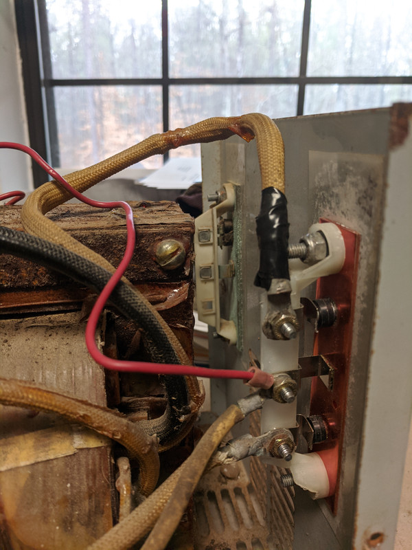 mouse test online mouse test online |
|
|
|
|
|
01-12-2021, 01:36 PM
|
#5 |
|
Techno-Nerd
Join Date: Jun 2011
Location: West Virginia
Posts: 19,654
|
The old diode assemblies had two diodes in parallel and two boards were used to make a full wave rectifier. The new diode assembly only has one diode for each leg of the transformer's secondary and is on one board. (Wiring diagrams for 17090 and regular Lestronic II attached.)
I suspect the original diode assemblies used two diodes in parallel to get the amp throughput needed because diodes of that type with a high enough amp rating was available at the time and I cannot see any part numbers on any of the diodes in the hi-res picture, so I'm not sure if any high amp diodes in the obsolete case design exist today. Check the new diodes with an Ohmmeter to see if they are still good. The heatsink mount on the charger case's rear panel, which is grounded via the AC power cord, so the output of the diodes has to be insulated from the rear panel. If it isn't and they are blown, there might be a lot of eddy currents in the transformer core, which is grounded to the AC power cord and may be the source the reason it is getting warm. I have a PW II that came with my cart and when I saw the unusual diodes used, I decided if it ever went out, I'd replace it with a 50A or so bridge rectifier, using only two of the four 50A diodes contained in the non-conductive case that could be mounted on the grounded rear panel with a single bolt and some heat sink compound for good heat dissipation. (Bridge rectifiers are cheap, only a couple dollars each for 50A 600V and not much more for 100A units) ------------ BTW: Your Pixel XL takes good pictures. How about taking some of the back side of the fuse assembly and ammeter and how they are connected together. |
|
|
|
|
01-12-2021, 04:42 PM
|
#6 |
|
Gone Wild
Join Date: Oct 2013
Posts: 413
|
Thanks again, Johnnie. I will take a picture of the rear of the fuse, but it will probably be tomorrow before I can do it.
I didn't use any sort of grease when I mounted the new heat sink and the diodes. I found conflicting info on whether or not that was necessary, and since I didn't have anything suitable, I tried it without it. When I removed the old heat sink, there was a layer of clear tape between it and the metal, and it appeared to still be in good condition. I just attached the new one to it and tried to tighten the screws evenly. Could that be what is keeping it from working, and could I have ruined my new diodes? I will test them when I remove the cover and make the picture. |
|
|
|
|
01-12-2021, 06:22 PM
|
#7 |
|
Techno-Nerd
Join Date: Jun 2011
Location: West Virginia
Posts: 19,654
|
I'm not sure why there isn't any output to the battery pack.
The first thing I'd do is measure the voltage between the two diodes. Jumper the relay on the control board so it doesn't have to be connected to cart's battery pack. Put the black test lead on the wire from the transformer going to one diode and the red test lead on the wire from the transformer going to the other one. Set meter to measure AC voltage. Should get about 90VAC with capacitor connected. (83 to 97 VAC is spec) Should get about 60VAC with capacitor disconnected. (55 to 65 VAC is spec) Be careful connecting/disconnection cap, it has nearly 500VAC on it. Unplug charger from AC power and discharge capacitor before disconnecting or reconnecting. If that is good, with meter set to DC voltage, measure from the red wire coming off the center terminal with red test lead to the one of the three wires connected to the fuse assembly. (If fuse links are good, it doesn't matter which of the three) ------------- Here is the manual for a regular Lestronic II. It has better troubleshooting explanations and pretty pictures showing what some of the tests. |
|
|
|
|
01-13-2021, 01:13 PM
|
#8 |
|
Gone Wild
Join Date: Oct 2013
Posts: 413
|
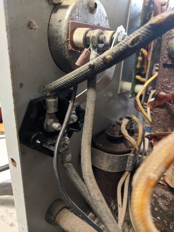
Johnnie, here is the picture you requested of the rear of the fuse assembly. I don't think there is a problem with this part:
 But, alas, I ran the diode test on my brand new board and it appears to me that the bottom diode was no good when I got it. I am not certain of this, but if I understand the test correctly, I should get at least a .450 reading on both diodes. The top one barely makes it at .454, but the bottom register OL. When I reverse the leads on the meter and put the positive lead on the center terminal, I get an OL reading on both diodes. My meter manual says that is what it is supposed to be. I guess the bottom diode isn't working? This is the diode assembly that I bought. It is listed as fitting the Lestronic II charger, but didn't list model numbers. Could it just be for the 20 amp model? https://www.amazon.com/dp/B074H1B6D9...ing=UTF8&psc=1 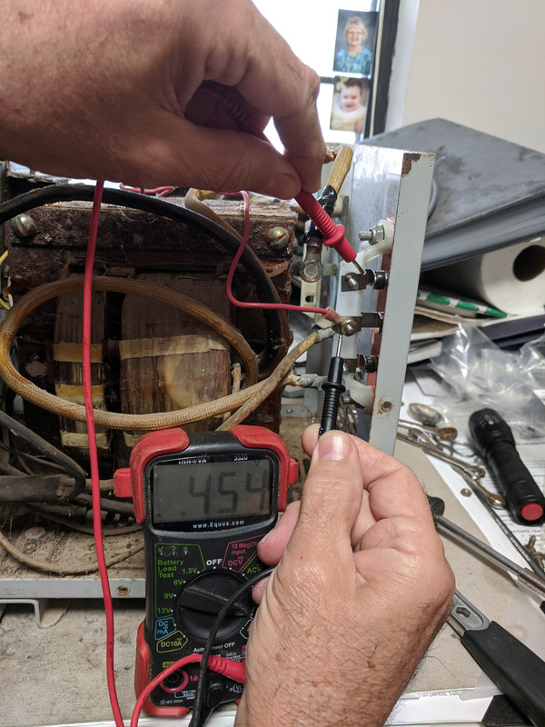 photos hosting photos hosting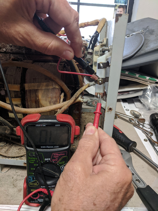 |
|
|
|
|
01-13-2021, 03:50 PM
|
#9 |
|
Techno-Nerd
Join Date: Jun 2011
Location: West Virginia
Posts: 19,654
|
The diode assembly has a bad diode.
I'm pretty sure is is for the 20A Lester chargers. I'm not sure why there isn't any output at all, but if you were just looking for the battery voltage to start climbing, it might not, or be very slow. --------------- I look for something that specifically stated it was for a 17090 charger, of at least gave some specs on the diodes, but didn't find anything. Looks like you've got two options. 1. Use two of the regular diode assemblies in parallel. That is basically what Lester did to get higher amp diodes. 2. Use two of the diodes in a bridge rectifier. I'd probably go with a 75A or 100A. Something like this: https://www.amazon.com/Baomain-Bridg...g%2C152&sr=8-3 Connect the wires from the transformer to the AC inputs and the output cable and sense wire to the "+" output. Leave the "-" output disconnected. Use some heatsink compound and mount on read panel. ------------ Nice meter - I have a 3340. |
|
|
|
|
01-13-2021, 07:19 PM
|
#10 |
|
Gone Wild
Join Date: Oct 2013
Posts: 413
|
Thanks again, Johnnie. Option 2 looks cheap enough to try, though I will probably need some more tutoring to hook it up. I found a place that shows the original part numbers, but they are $75 each and I would need 2 of them, so it will go on the junk pile before that happens.
Will this work for the compound? https://www.amazon.com/dp/B078RNBFMG..._Mf5.Fb2K47DXK |
|
|
|
|
|
||||||
| Thread Tools | |
| Display Modes | |
|
|
 Similar Threads
|
||||
| Thread | Forum | |||
| Last attempt at a little more speed | Electric EZGO | |||
| Should I attempt to obtain a Villager 4? | Electric Club Car | |||
| First Attempt at painting a Club Car | Lifted Golf Carts | |||
| Rear seat, first attempt | Gas Yamaha | |||
| First attempt at posting pics | Test Post | |||


 Linear Mode
