
|
|
|||||||
| Electric EZGO Electric EZ GO Marathon, Medalist, TXT and RXV. |
  |
|
|
Thread Tools | Display Modes |
 11-06-2011, 01:42 AM
|
#1 |
|
Not Yet Wild

Join Date: Oct 2010
Location: Buckeye, AZ
Posts: 74
|
I blew one of the two 40A fuses in the charger for my 1983 Marathon. Without thinking about it, I pulled both fuses and did not label which one goes where.
 I now have two working fuses FNM-40 and KTK-40 but don't know where they go. The slots for the fuses are right next to each other. One of them is closer to the outside edge of the charger and the other is closer to the inside of the charger. Which fuse goes into which slot? Thanks for the help!  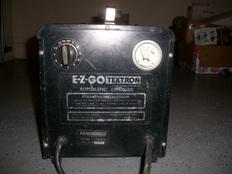  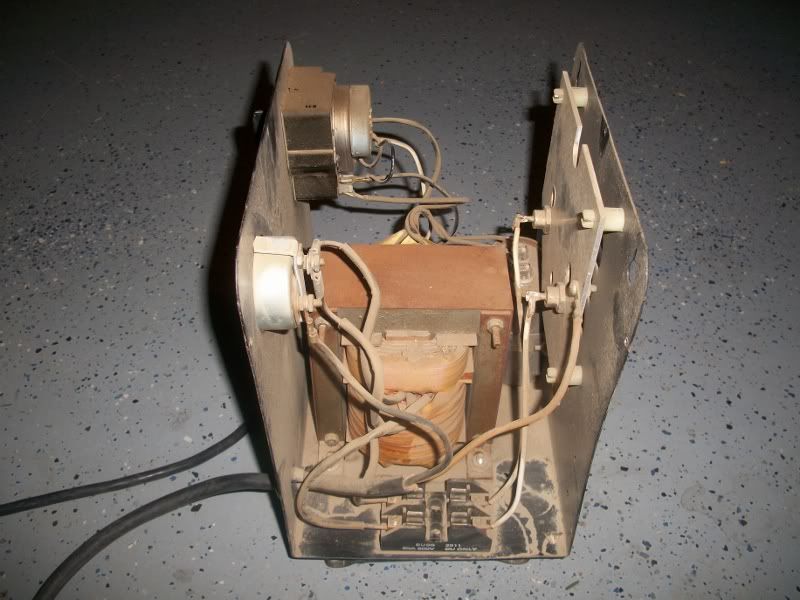 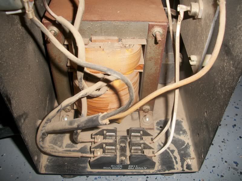 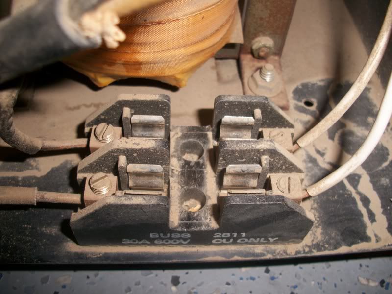 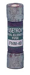 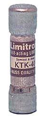 |

|

|
 Today Today
|
|
|
__________________
This advertising will not be shown in this way to registered members. Register your free account today and become a member on Buggies Gone Wild Golf Cart Forum |
|
|
11-06-2011, 06:03 AM
|
#2 |
|
Techno-Nerd
 Join Date: Jun 2011
Location: West Virginia
Posts: 19,654
|
First of all - Thank you for posting the pictures. It takes (most of) the guesswork out.
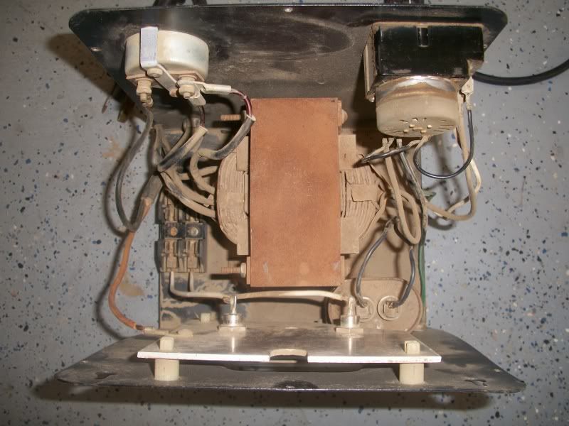
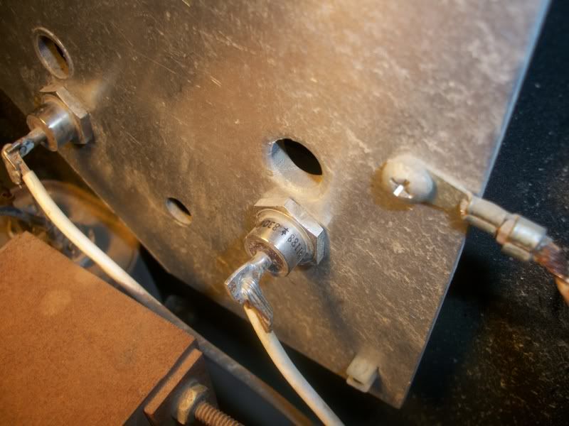
 It doesn't matter which fuse goes where. If you follow the wires from each end of each fuse holder in picture #3, the black ones go to the transformer and the white ones go to the diodes, so each fuse is performing the same function, only on a different diode. Both fuses were identical originally, but I don't think they were 40A since the rating printed on fuse-holder is 30A. Also, you've got one "Fast-Acting" and one "Slow-Blow" fuse, but I don't know which style was originally installed. My guess is that the originals were 30A Slo-Blo, but what you've got will work until you can find them. Whenever a charger blows a fuse, always test the diodes before installing new fuses since a shorted diode is the most likely caused of a blown fuse in a charger. If you don't know how to test the diode, give a shout back. Now, I've got a favor to ask. Please take a couple more pictures of you charger with cover off and post them. (I want to see what is on the other side of the transformer.) 1. Top View 2. Same angle as #3 except from opposite side. (Timer side instead of Ammeter side) The front panel says it is an "Automatic Charger", but the operating instructions printed thereon, implies it is a manual charger that runs on a timer. I'd like to find out which it is and a picture showing what is on the other side of the transformer would do the trick. |
|
|
|
|
11-06-2011, 05:53 PM
|
#3 | |||
|
Not Yet Wild
Join Date: Oct 2010
Location: Buckeye, AZ
Posts: 74
|
Quote:
Quote:
Quote:
    |
|||
|
|
|
|
11-06-2011, 07:25 PM
|
#4 |
|
Gone Wild
Join Date: Aug 2011
Location: Bunnell, Florida
Posts: 2,408
|
First, make sure the power cord is unplugged and the fuses are removed. Take one lead of a continuity tester, or DMM on resistance scale, and place it on the plate the diodes are mounted in.Touch the other lead to the wire connected to each diode in turn. Now reverse the two leads and do the same thing again. A continuity tester should show a current flow in one direction only, for both diodes. Using a resistance scale on a DMM should produce the same result, except there should be a high resistance reading in one direction, and a low resistance reading in the other. If the diodes pass current both directions, they are bad. If they pass no current either direction, they are bad. In the event the diodes are bad, they're not real expensive.
|
|
|
|
|
11-07-2011, 08:16 AM
|
#5 |
|
Techno-Nerd
Join Date: Jun 2011
Location: West Virginia
Posts: 19,654
|
Simple man covered it well.
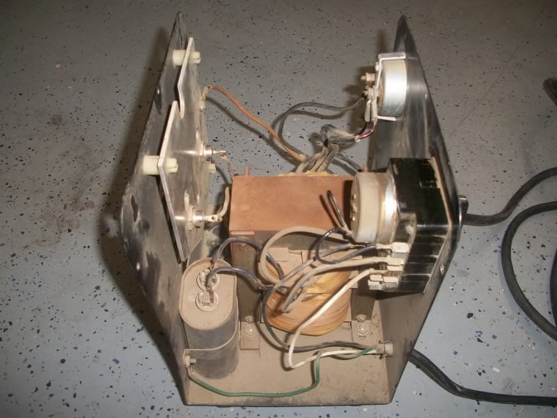
Thanks for the additional pictures showing what's on the other side of the transformer. Now I know exactly how it works. ON/OFF is controlled by the timer alone. Battery voltage plays no role in turning it on or off, so if you connected it to a watermelon, it would try to charge it. Not saying that you would, but if somebody somehow connected it to a car battery, they would get an acid bath when the 12V battery exploded. That's probably one of the main reasons later versions of 36V chargers sensed battery voltage to turn on. (Wonder how many lawsuits that change took) The Transformer and Capacitor arrangement used, does "automatically" regulate the output current to the battery, so the term "Automatic Charger" on the faceplate isn't actually incorrect, but the term took on a new meaning when later chargers sensed battery voltage to turn on and off, so now it is a misnomer. |
|
|
|
|
11-08-2011, 08:36 PM
|
#6 | |
|
Not Yet Wild
Join Date: Oct 2010
Location: Buckeye, AZ
Posts: 74
|
Quote:
|
|
|
|
|
|
11-08-2011, 10:01 PM
|
#7 | |
|
Gone Wild
Join Date: Aug 2011
Location: Bunnell, Florida
Posts: 2,408
|
Quote:
|
|
|
|
|
|
11-09-2011, 01:25 AM
|
#8 | ||||
|
Not Yet Wild
Join Date: Oct 2010
Location: Buckeye, AZ
Posts: 74
|
Quote:
How to test a diode video Quote:
Quote:
Quote:
Before the fuse blew I was putting the cart back together and moving batteries around. I thought I double checked everything, but there is the possibility that I reversed the polarity of the cables coming from the charger receptacle on the cart. That I know would blow a fuse for sure. Well, I tested everything I know to test. Looks like I will have to bite the bullet and try it out with the new fuses. Thanks everyone for your help. I'll let you know how it goes. |
||||
|
|
|
|
11-09-2011, 08:15 AM
|
#9 |
|
Techno-Nerd
Join Date: Jun 2011
Location: West Virginia
Posts: 19,654
|
Back in the VOM days, we didn't have to worry about such things since the voltage put out by the meter to test resistance was equal to at least one Carbon-Zinc cell (1.5V) or more. However some geeks and nerds started shrinking things down in physical size and pretty soon they had P/N junctions (Diodes among other stuff) that can't tolerate that high of voltage, so the geeks and nerds that invented DMMs limited the voltage used to measure resistance, which is the reciprocal of continuity. In fact, the voltage used by some modern DMMs is so low it won't forward bias the silicon P/N junction found in nearly all the discreet diodes found in use today and they read the same in both directions.
Long story short. If your DMM has resistance and/or continuity settings marked with a diode symbol, use those settings when checking diodes. High resistance (low continuity) in one direction. Low resistance (High continuity) in the other. 10 to 1 ratio or more. Turblown - If no decimal point was showing and no multiplier (K or M) was showing on the display, it was Ohms. One has to be careful with auto-ranging meters or they'll take a bite out of your intellectual backside when you least expect it. (Don't ask how I know The nutty thing is that different DMMs will give you different Ohms values on the same diode. The reason is fairly simple: A forward biased P/N junction is a voltage regulator (0.6V for a silicon diode) so current through it varies while voltage drop across remains constant. How the DMM designers chose to cope with that electronic curve-ball determines the Ohms reading. Make sure the output cables are going to the right places and give it a "Smoke Test". (If the smoke doesn't leak out, it's good to go.) |
|
|
|
|
11-09-2011, 09:48 AM
|
#10 |
|
Gone Wild
Join Date: Aug 2011
Location: Bunnell, Florida
Posts: 2,408
|
Thanks " JohnnieB " for an accurate and detailed description of something I didn't know! I have an old Micronta DMM and it measures diodes fine on the Ω scale. I had no clue newer meters are different!
@ " turblown " I apologize for the screw up. I just assumed all meters functioned alike. I'm sorry to have caused you extra work on your diagnosis! |
|
|
|
|
|
||||||
|
|
 Similar Threads
|
||||
| Thread | Forum | |||
| Ezgo powerwise charger blowing fuses | Electric EZGO | |||
| ezgo textron charger question | Electric EZGO | |||
| EZ_GO Textron charger on '88 36 volt cart | Electric EZGO | |||
| EZGO/Textron 36V charger | Golf Carts and Parts | |||
| Textron golf cart charger wiring | Electric EZGO | |||


 Linear Mode
